Tagged: invetsigation

From Measurement to Action

Start measuring the air in your system. The most useful air-in-oil measurement is not the one that produces the largest number of parameters. It is the one that supports a better engineering process.

  • Define a representative baseline.
  • Detect a meaningful deviation.
  • Interpret it together with fluid, component, and operating context.
  • Investigate the most plausible mechanism.
  • Verify whether the intervention changed the measured behavior.

Many practitioners only view air as an issue when they see foam. By this time, it is too late and damage has already occurred to the system. Even small bubbles can have system consequences, as shown in the diagram below.
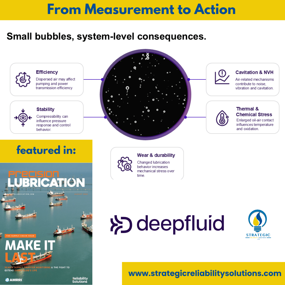
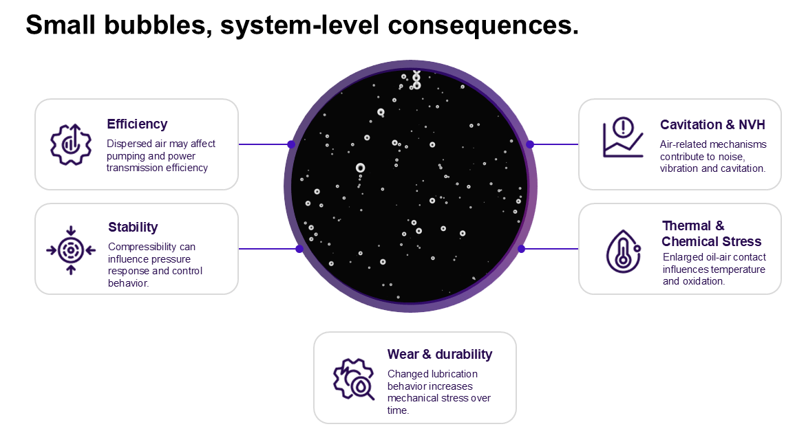
figure 6
Figure 6: System-level consequences which can be detected by the presence of small bubbles through deepfluid’s technology

Many operators are not aware of the impacts of air-in-oil and quite often, it is labelled as something else. However, it usually shows up as a foam problem, unexpected NVH, control instability, temperature problem, cavitation problem, pump problem or an oil problem. The key is to monitor these effects in different settings.

Starting with studying air release, dispersion and formulation effects under controlled conditions in the lab. Moving to the testing phase where bubble behaviour is related to operating conditions, design changes and system response. Then finally to the field where changes can be tracked over time to support root-cause analysis and confirm any improvements.

This is the benefit of using the deepfluid technology as it can capture data from the various phases to bring about actionable insights to improve the reliability of operating systems.

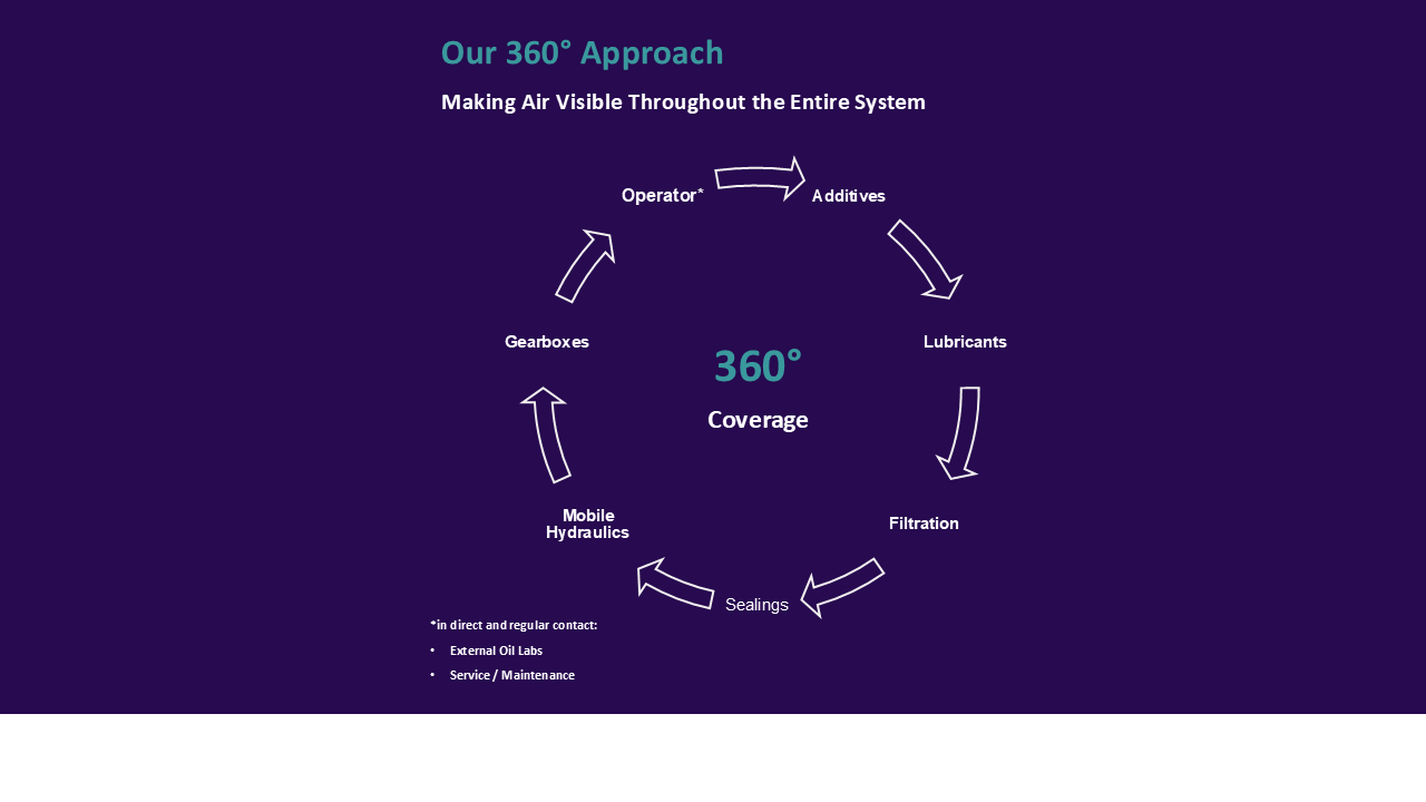
The 360 Approach – One Shared Data Language Across the Lubrication Value Chain

At Deepfluid, they have adopted a 360 approach where they can assist all the stakeholders involved in the lubricant industry as it relates to the oil being in the equipment. It connects formulation development, laboratory testing, component testing, system validation, field operation, maintenance, troubleshooting, and verification of corrective actions.

With the 360 approach, various stakeholders can be involved to ensure that the lubricant is fully assessed in different situations, from the testing and development of the lubricant to its actual application in the component then finally to the end user by ensuring they get the results they need.

An additive supplier may investigate formulation effects. A lubricant manufacturer may compare air-release and foam behavior. A filter or seal supplier may study aeration or air ingress. An OEM may correlate bubble behavior with efficiency, thermal management, or NVH. An operator may investigate an abnormal field deviation. An external oil laboratory or research institution may provide controlled reference analysis.

The questions differ, but the underlying air-in-oil metrics can remain comparable.

Not one product for every stakeholder, but one measurement logic that allows different stakeholders to work on the same fluid-system question from different positions in the value chain.

The 360 approach ensures that all aspects are taken into consideration for the oil, from the lab testing to the field development, with all the stakeholders involved. This guarantees that the final product is reliable and the user should have a valuable experience.

Case Study – From Abnormal Air-in-Oil Data to a Targeted Seal Investigation

Deepfluid’s direct measurement system can be used not only to analyze the interaction between oil and air during operation but also to monitor the overall system behavior and the reliability of the installed components.

The leak-tightness of hydraulic circuits is essential and critical for the safe operation of these systems. Leaks can allow air and particles to be drawn into the system under negative pressure and oil to be forced out of the system under positive pressure. The presence of air significantly alters operating behavior by changing viscosity, density, fluid level, and lubricating film thickness. These factors can lead to damage such as pitting, scuffing, and micro-dieseling.

If an operator or service technician frequently inspects an application’s oil tank—either directly or through large sight glasses—high air content can be detected by significant cloudiness in the oil.

However, if the application’s oil tank is located in a hard-to-reach position, operates autonomously, or is only accessed during shutdown, such extreme conditions are detected very late, in the laboratory—if at all—before costly damage occurs. This is the case with the operation of wind turbines. Although speed, torque, temperature, particle content, and potential oil leaks are detected, suction-side air ingress, for example, cannot be detected.

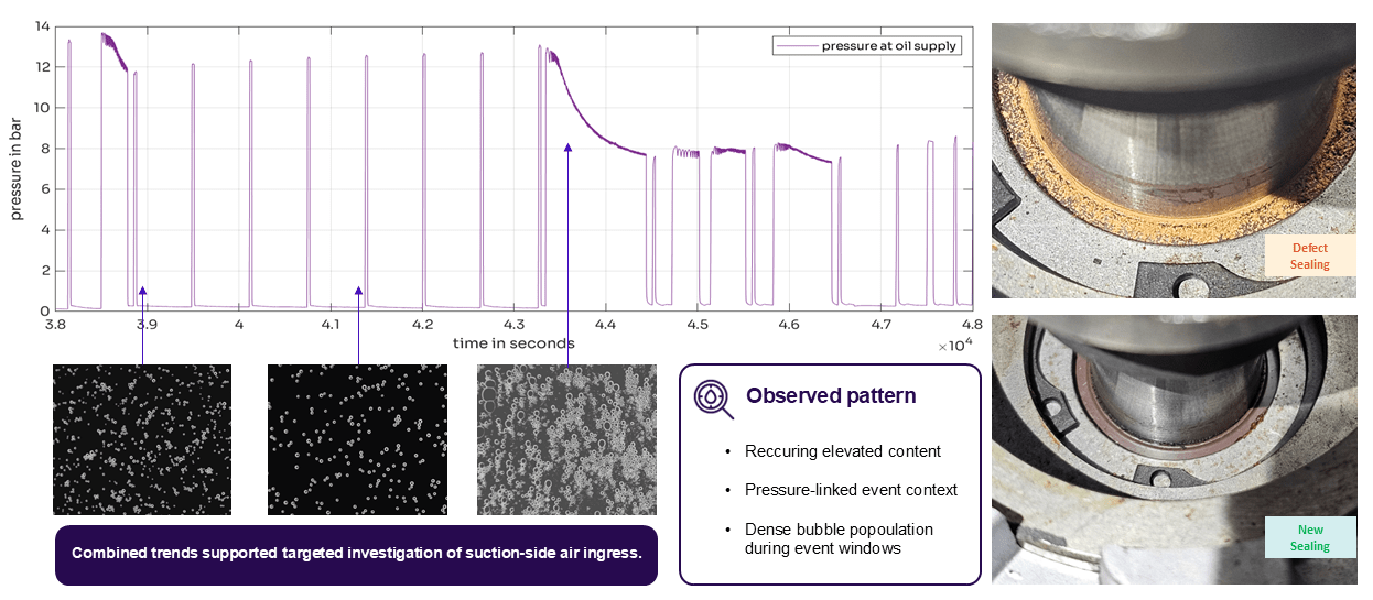
figure 5A
Figure 5A. Recurring Air-in-Oil Deviation During Gearbox Operation. A synchronized view of air content, pressure context, and bubble population illustrates how recurring events can support a targeted investigation of possible suction-side or sealing-related air ingress.

In the case study presented, a defective shaft seal was detected through direct measurement on a supply pump for the injection lubrication system of a wind turbine, based on an iteratively and periodically occurring very high air content and loud noise. A minor issue that can have serious financial consequences.

Risks posed by excessive air content and their costs, using a 2.5 MW turbine as an example:

  • Higher operating temperature, which requires additional cooling
  • Increased cooling capacity (between 4.9 kW and 9.4 kW) due to reduced thermal conductivity (0.14 W/(mK) → 0.125 W/(mK)), costing between 7k€ and 10k€ per year
  • Change in friction conditions in conjunction with increased cooling capacity: 43k€–82k€ per year
  • Risk of faster oil aging due to accelerated oil oxidation and thermal oil oxidation: 1 additional oil change (24k€–60k€)
  • Total mechanical failure of the main gearbox renders the entire system uneconomical.

In this component, there was persistently high air content which we are able to identify and link to abnormal ingress of air into the lubrication system. However, we also saw the pressure drop during pump operation. This was an indicator for suction-side or sealing-related air ingress. We also noticed a dense bubble population which indicates critical oil-air dispersion under operating conditions. There was a deviation from a similar gearbox indicating that this was a system-specific malfunction rather than normal behaviour.

If these were not identified at this early stage, the equipment would run the risk of micro-dieseling, cavitation, oxidation and temperature increase. This would lead to mechanical damage in the gearbox or oil supply components, eventually leading to reduced lubrication reliability and accelerated wear.