Category: Reliability

Turning Air Measurements Into Reliability Insight

The Smart Bubble System, developed by Evamo, allows users to gain deeper insight into the behavior of air in their oil. It turns a general volume-based quantification into actionable metrics to improve your system’s reliability and performance...

How Is Air in Oil Measured?

When we think about measuring air in oil, the top-of-mind lab tests that are well known are the foam test (ASTM D892) and the Air Release test (ASTM D3427 & DIN ISO 9120). While these two tests can provide information on the tendency of foam to dissipate or for air to be released from the oil, they don’t give the entire story of what’s happening in the oil as it relates to air...

The Chemistry Behind Air in Oil

The oil’s chemistry also plays a significant role in determining its air content. All finished lubricants consist of base oil and additives. The characteristics......

How Does Air Get Into Oil?

Air is inert, so it shouldn’t affect your oil, right?! This is a concept that many people get wrong or don’t fully understand. Air......

Role of Condition Monitoring, Human & Organizational Factors in Oil Failures

Choosing the right oil for the system is just one part of the puzzle. How do we know the oil is performing when it’s......

Common Modes of Failure for Lubricants

Regardless of the oil selected, common modes of failure can occur with every lubricant. These include: contamination, improper storage and handling practices, and environmental......

Spec Sheet vs Strategy for choosing the right oil

Sometimes we can spend hours poring over technical data sheets, comparing oil performances, and finally selecting the “right” oil which aligns with the needs......

Varnish Badges of Honour

Varnish is widely known as a primary culprit of equipment failure. This sticky enemy effectively finds its way into most of our equipment and......

My MLE Journey

Some details about the MLE certification journey from online classes to online exam...

EasyRCA!

Recently, most of our concerns stem around getting stuff done faster but wanting the same quality result. For instance, when loading a web page,......

ICML 55 – the revolution in the lubrication sector

What is ICML 55? ICML 55 is revolutionizing the lubrication industry! It is so exciting to be around at this time when it has......

5 Habits of an Extraordinary Reliability Engineer – My review

Peter Horsburgh has essentially captured the 5 Habits of an Extraordinary Reliability Engineer in his book! His style of writing appeals to engineers as he keeps......

PROACT Review

Root Cause Analysis has always been dear to my heart. The procedure involved in finding the root causes and addressing them have intrigued me greatly......

No post found

Turning Air Measurements Into Reliability Insight

The Smart Bubble System, developed by Evamo, allows users to gain deeper insight into the behavior of air in their oil. It turns a general volume-based quantification into actionable metrics to improve your system’s reliability and performance. The SBS captures the following metrics:

  • Bubble diameter
  • Air content in your system
  • Bubble count
  • Bubble size-distribution
  • Oil-Air contact surface
  • Transient bubble events

These metrics are directly related to what users see in the field. As such, it closes a gap that many users often experience when relating lab results to field integrations. Users can also trend whether the number of smaller bubbles increased, whether large bubbles began to form in their system, or whether there were transient spikes due to particular conditions in temperature, load, speed, or even return-flow conditions.

Here are a couple of examples that highlight how these values can be interpreted in the field:

  1. If a rise in fine-dispersed bubbles occurs, then this can be indicative of persistent gas transport through the system. This affects the oil’s compressibility and can even lead to a stability issue.
  2. If there is a rise in the number of larger bubbles, this can indicate that there is localized entrainment, return-line impact, free-surface interaction, and stronger ingestion events. If these are not addressed in time, they can damage your components.
  3. If one detects an increase in oil-air contact surface, this can indicate that gas distribution has become more degradation-relevant in the system. This may be despite no dramatic change in the total air content.
  4. If transient bubble events are present, this can directly point to issues related to specific operating states rather than a general system condition that needs to be addressed.
  5. If smaller bubbles occur, this leads to much worse thermal conductivity. As such, higher operating temperatures would need to be cooled down directly with a high amount of energy, or this can lead to a much higher thermal oxidation rate. In each case, the system efficiency is reduced.

These observations set the stage for more in-depth analysis and contextual interpretation to determine whether the pattern is fluid-driven, hardware-driven, or operating-point-driven. A workflow can be easily implemented to reduce risks to your operation, as highlighted in Figure 3 below.

Figure 3: Suggested workflow for monitoring air in your oil

A robust methodology for the characterization and optimization of your system should follow a structured measurement and interpretation workflow:

  1. Definition of the System Baseline
    The first step is to establish a representative baseline condition by continuously measuring the system’s actual operating state. These parameters should include temperature, rotational speed, torque, flow velocity, pressure conditions, and load states. The baseline must capture the dependency of the oil–air behavior on these operating variables to provide a reliable reference for subsequent evaluations and further steps.
  2. Detection of Deviations and Dynamic Transitions
    Deviations from the baseline are identified using real-time monitoring metrics and transient analysis. Changes in aeration behavior, bubble content, or flow characteristics are quantified relative to the reference baseline state established in Step 1. In parallel, a prioritization strategy should be defined to identify the most critical deviations and focus optimization efforts on the parameters with the highest system impact.
  3. Contextual Interpretation of Deviations
    Detected deviations must be interpreted within the system’s physical context. The origin of the observed behavior should be determined by correlating the measured size distribution and temporal system response with potential mechanisms such as splashing, churning, vortex formation, temperature variations, fluid aging, or changes in the operating point. This contextual analysis enables the differentiation between transient operational effects and systematic design-related issues.
  4. Implementation of Targeted Corrective Measures
    Based on the contextual interpretation, focused and goal-oriented design modifications can be implemented. Possible optimization measures include adjustments to return-flow geometries, improvements in suction conditions, reductions in churning effects, optimization of pressure levels, speed or load adaptations, fluid conditioning, changes to additive formulations, or enhanced filtration strategies. The corrective actions should directly address the identified root causes of the aeration behavior.
  5. Validation Through Continuous Measurement and Improvement
    The effectiveness of the implemented measures must be validated through continuous monitoring and iterative evaluation. Repeated measurements under comparable operating conditions ensure that improvements are sustainable and quantifiable. This closed-loop approach enables continuous system refinement and supports long-term optimization of the behavior of oil–air mixtures.

By moving beyond the standard quantitative measure of air in oil, we can address critical issues occurring in our equipment.  By measuring and interpreting metrics correctly, you can optimize your system’s overall performance, make it goal-oriented, and keep it focused. This supersedes the often-used trial-and-error approach, which can ultimately damage your equipment.

For those interested in taking a more serious approach to understanding the health of their oil and preventing issues before they occur, the SBS can help improve the reliability of their system.

What you see is what you get!

How Is Air in Oil Measured?

When we think about measuring air in oil, the top-of-mind lab tests that are well known are the foam test (ASTM D892) and the Air Release test (ASTM D3427 & DIN ISO 9120). While these two tests can provide information on the tendency of foam to dissipate or for air to be released from the oil, they don’t give the entire story of what’s happening in the oil as it relates to air.

More specifically, they do not take into account the volume of air that can be trapped in your system during operation, nor how long it will take to dissipate when everything stands still. These parameters are critical for determining the impact of entrapped air in your oil.

People can also measure the volume of air in the oil, but 5% can mean different things depending on the air’s state, as shown in Figure 2 below.

Figure 2: Scenarios where the air (gas) volume of 5% can mean different things

As we can see in Figure 2, an air (gas) volume fraction of 5% may appear the same, but it can affect your system differently.

In Scenario A, the bubble sizes are larger, so these will rise to the surface more quickly and dissipate. As such, there are fewer disturbances and pressure fluctuations.

In this case, these might indicate localized entrainment, suggesting churning or impact from your return line. Another source could be coalescence, driven by oil properties, splash effects, and other factors. The risk of air bubbles becoming trapped in dead zones increases.

However, in Scenario B, the average bubble size is smaller, which means there are many more air bubbles in the oil! This means that there is a higher surface contact area and an increased potential for foaming. This can increase the rate of oxidation and, by extension, the risk of the oil forming varnish.

This also significantly affects the oil’s compressibility. With the advent of these smaller bubbles, there is usually system-wide aeration, such as vortexing or suction issues. The risk of inefficient cooling and overheating your oil in heaters has increased significantly.

With only a 5% air volume result, we would be missing critical information, such as what could be causing the issue or whether it is an immediate threat to our operations. This is where the SBS (Smart Bubble System) changes the entire game.

The Chemistry Behind Air in Oil

The oil’s chemistry also plays a significant role in determining its air content. All finished lubricants consist of base oil and additives. The characteristics of your base oil can determine important factors such as your viscosity, interfacial behavior, density, and gas solubility. The surface tension of your oil can also be affected by the size of the bubbles and how long they stay in that formation of the bubble.

Depending on the oil application, the appropriate ratios and types of additives vary. As such, there may be more emphasis on certain characteristics such as oxidation stability, viscosity behavior, or foam control. These additives all affect how long air can remain in the oil and the oil’s state, which can affect our machinery.

As shown in the video below, we can compare the air content percentage of an oil at varying temperatures and observe significant differences.

As shown in the first video, for a wind turbine gearbox using Optigear Syn CT320, the oil contains less air as the temperature increases, decreasing from 2% at 80°C to 0.7% at 110°C. At 110°C, we see a further decrease in air content to 0.65%. As the temperature starts decreasing again toward 80°C, we observe a volume with 2.2% air content in the oil. This is simply due to a temperature change in the oil, not to any additional air ingress.

As such, for the Optigear Syn CT320 oil in this wind turbine gearbox application, we can conclude that if the oil operates at temperatures around 80°C, we can expect up to 2% air volume in the oil. We observe that for lower temperatures, the air content may increase due to the impact of viscosity on air-release capability.

But if the temperatures increase (to a temperature that is tolerated within the system), then the volume of air will decrease, which is a good thing. However, as temperature increases, your chances of thermal and non-thermal oxidation also increase.

In the video above, we see a completely different behavior with the Fuchs Titan EG ATF D VI oil in an automotive gearbox, which starts off at 45 °C. There is a low air volume in the oil at 0.1%. However, when the temperature reaches 73°C, the volume of air increases by 0.7%.

The air bubbles are much larger, increasing the contact surface and their count within the oil. As the temperature decreases to 49°C, the volume decreases by 0.4%, and the number of bubbles decreases. With the continued drop in temperature to 44°C, the air volume decreases to 0.2% and then tapers off to 0.1%, with smaller, fewer bubbles.

In a wind turbine gearbox application using industrial gearbox oil, we observe that the air content decreases as temperature increases. Conversely, in an automotive gearbox using transmission gear oil, the air content increases with rising temperatures. This is very specific to the oils tested in these examples, as different oils will have varying ratios and types of additives and base oils, which can be affected in diverse ways.

The chemistry of the oil is, therefore, another critical part of understanding the air in your oil. If this is properly understood and measured, it can be very useful for monitoring your oil’s health in the field.

How Does Air Get Into Oil?

Air is inert, so it shouldn’t affect your oil, right?! This is a concept that many people get wrong or don’t fully understand. Air in your oil can literally cost your facility millions of dollars in damage if it is not treated or removed from your system early.

It can affect the compressibility of your oil, its thermal behavior, and the oxidation stability of hydraulic and drivetrain systems, leading to degradation or efficiency loss. With reduced efficiency, overall production will decline, which can negatively impact the profitability of your operations. Before we dive into the ways it can affect your system, we need to understand the basics.

The Four States of Air in Oil

Air can exist in four states within your oil and machine. As shown in Figure 1, these include;

  • Dissolved air
  • Entrained air
  • Foam
  • Headspace interaction
Figure 1: Different states in which air exists in your system

Each of these states can affect your system differently, as shown in the table below, and will have corresponding sources of ingression.

Reliability Meaning for Various States of Air

State Reliability Meaning Typical Sources
Dissolved Air – this usually represents 8-12% of dissolved air at atmospheric pressure Affects solution chemistry.

Can come out of solution when pressure, temperature or shear conditions change.

Often a hidden source for future entrained air.

Equilibrium with headspace air usually in the sump, make up oil (when oil is added to the sump), storage, temperature or pressure changes.
Entrained Air Reduces effective bulk modulus (compressibility).

Has a big impact on control stability, efficiency, and thermal behaviour.

Drives cavitation and microdieseling risk.

Even with a 0.5% volume of air, this can triple the risk of varnish.

Controllability of valves gets affected.

Maximal suction height of pumps is reduced dramatically.

Suction leakage, vortexing, return-line splash, churning, gear mesh aeration, system design. However, strong pressure reductions lead to de-aeration of the dissolved air.
Foam Indicates strong surface activity or contamination.

Can reduce effective oil volume, impair heat transfer and promote aeration carry-over.

Surface active additives, detergents, contaminants, high turbulence, agitation.
Headspace Interaction Drives how much air enters or leaves the oil over time. Influenced by temperature, pressure, ventilation and oil level. Breathers, vents, temperature cycles, pressure changes, low oil level.

For each of the states above, air affects the reliability of your equipment. It is critical to identify the state of air in your oil so it can be removed before it begins to affect your system. Typically, maintenance teams pay attention to air in oil only when it is visible (foaming) or when it demands their attention through noisy interactions. By this time, teams have lost the opportunity to remove the air while it is in its more benign state.

How Does Air Get Into Oil?

When we think about air getting into our oil, we generally think of openings or mechanical areas that allow it to enter. However, air can enter our system in several ways. It is also worth noting that air already exists in the oil at equilibrium, where it will leave the oil according to Henry´s law.

Air can become entrained (or trapped) in the oil through various mechanisms such as return-line splash, vortex formation, suction-side leakage, tank dynamics, free-surface interaction, or churning in gearboxes and drivetrains. When entrained, it can cause damage to your equipment if not detected in time.

Changes in operating regimes can also influence whether air stays in the oil or gets forced into it. This is usually seen with changes in pressure, temperature, or shear conditions. Within your system, your oil can experience a load transition, a change in oil level, or return flow, all of which can influence the volume of air that remains in or enters your oil.

Even after identifying the source of air ingress, it is imperative that it be removed from your system. While air in oil does not usually get the attention it deserves, it will demand that attention if it goes unresolved or remains in your system.

Role of Condition Monitoring, Human & Organizational Factors in Oil Failures

Choosing the right oil for the system is just one part of the puzzle. How do we know the oil is performing when it’s in the system? This is where condition monitoring can work hand in hand to help ensure that the oil does not fail the asset.

If a proper oil analysis program does not exist, operators will not know whether the oil is properly lubricating the asset. They will also not be aware of whether the oil is breaking down too quickly and failing to protect the asset. Oil analysis can also alert operators to signs of wear in the asset, so they can fix them before they turn into functional failures.

An oil analysis program that lives in a drawer protects assets about as well as no program at all.

There is also the possibility that an oil analysis program exists but is not top of mind, or that its results are put in a drawer. This can also cause the asset to fail even though the correct oil is being used. Apart from the aforementioned factors, if operators are not warned of the impending failure of the oil, this can result in production losses, increased downtime, and, in some extreme cases, the complete loss of the asset if it has failed beyond repair.

Incorrect sampling is another area in which the actual condition of the asset is not reported. Even with the correct oil used, if a sample is collected from a dead leg or an area that is not truly representative of the conditions inside the component, its actual condition will not be known. With incorrect data about the component, the asset can be misdiagnosed or treated for symptoms that do not exist, which can lead to its detriment.

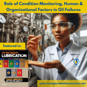
Human and Organizational Factors

Not all failures occur at the equipment level; human and organizational factors can also cause the asset to fail even when the correct oil is used. If humans aren’t properly trained in oil sampling techniques or storage and handling practices, these can affect the asset’s functionality. We often forget that, at the heart of it all, lies the human factor, which is partially governed by the organization’s systems.

Training needs are an organizational factor that is often overlooked when considering how an asset can fail. However, if operators have not been trained in condition monitoring techniques, they will not be able to read oil analysis reports or take appropriate actions to protect the asset. Training can help bridge some competency gaps that directly impact asset performance.

It doesn’t matter what oil is in the system if no one is trained to monitor it – or motivated to care.

Culture is another factor swept under the rug. If the culture doesn’t exist to look after the assets, it doesn’t matter what type of oil is placed in the system; the asset will fail eventually. The performance of the asset does not only rely on using the correct oil. By implementing a culture of Asset ownership, where operators look after the asset and are accountable for its performance, assets are optimized to provide the functionality they should. This is one way to ensure the right oil is used to enable the assets’ performance.

Another area of concern is the documentation of maintenance procedures. If maintenance procedures are not adequately documented, someone new to the operation may not be aware of the correct practice. This, coupled with a lack of training, can spell disaster for the equipment. In these cases, even though the right oil was selected, the wrong practice or lack thereof can fail the asset.

Turning the “Right oil” into the “Right Outcome.”

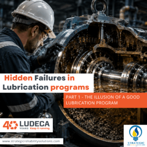
As explained in this article, improper practices can jeopardize the asset’s health, even when the right oil is used. However, if all the right things align, we can have an asset that lasts for its expected lifetime or beyond.

This starts with selecting the right oil based on the application, environmental conditions, and OEM recommendations. If we follow this up with good storage and handling practices, proper condition-monitoring programs, documentation, and training, we can look toward a longer-lasting asset. The right oil enables reliability – but only disciplined practices deliver it.

Find out more in the full article, "When 'Right oil, Wrong practice' still fails assets" featured in Precision Lubrication Magazine by Sanya Mathura, CEO & Founder of Strategic Reliability Solutions Ltd. 

Common Modes of Failure for Lubricants

Regardless of the oil selected, common modes of failure can occur with every lubricant. These include: contamination, improper storage and handling practices, and environmental factors as shown in Figure 4.

Figure 4: Common modes of failure for lubricants

Contamination can be defined as any foreign particle entering the system. This includes any gases, liquids, or solids. Especially when the lubricant system runs alongside the process side, process gases and liquids can leak into the oil. These contaminants can influence the oil’s degradation, leading to deposits or chemical reactions that break it down. Common process contaminants include ammonia or treated water.

The biggest threat to the right oil is often what gets added to it – whether it’s process contamination or the wrong oil during a top-up.

Another liquid that can contaminate oil is another oil. During top-ups, operators can add the wrong oil to the system, causing contamination and, depending on the oil, a possible shutdown. Adding motor oil to hydraulic oil can be catastrophic, as the additive packages work differently and the motor oil additives may counteract the hydraulic additives, removing them from the oil, leaving the asset open to wear and failure. Despite selecting the correct lubricant for your system, adding the wrong oil (mistakenly) will shorten its lifecycle and cause the asset to fail.

Bad storage and handling practices can also erode your oil, regardless of the oil you choose. Turbine and hydraulic oils are used in precise equipment. As such, they need to be clean and free of dirt or other contaminants. However, if oils are not stored correctly, contaminants can enter and contaminate the oil.

Simple techniques, such as transferring oil from larger storage containers (pails, drums, or totes) into smaller, more manageable containers (2-3 liters or less), can introduce contaminants into the oil if not done correctly. If oils are to be transferred to another storage container, the storage container must be clean. The transfer process should use clean hoses (not previously used for another lubricant) and be completed in a dust-free environment.

If you wouldn’t use a dirty needle for a blood transfusion, why would you use a dirty hose for an oil transfer?

The transfer of oils from one container to the next can be thought of as a blood transfusion. Would you use dirty needles or vials to transport the blood to be placed into another human? Similarly, oil can be likened to the equipment’s lifeblood and should be treated accordingly. Just as we observe sterile practices for blood transfusions, we should also observe similar types of practices for oil transfers.

Environmental and operational factors can also influence lubricant degradation. As stated earlier, all lubricants can degrade over time under harsh conditions. The lubricant formulation largely influences this, as does whether it was blended to withstand those conditions.

Oxidation can easily occur when temperatures increase, free radicals are present, or when wear metals are present. Thermal degradation occurs when the temperatures exceed 200°C. On the other hand, microdieseling occurs in the presence of entrained air, despite the lubricant used in the system, as shown in Figure 5.

Figure 5: Lubricant Degradation Processes

Any of these degradation mechanisms can occur regardless of the type of oil chosen. Hence, it is essential to remember that operational conditions and environmental factors can heavily influence oil degradation, even when the oil is appropriate for the system.

Find out more in the full article, "When 'Right oil, Wrong practice' still fails assets" featured in Precision Lubrication Magazine by Sanya Mathura, CEO & Founder of Strategic Reliability Solutions Ltd. 

Spec Sheet vs Strategy for choosing the right oil

Sometimes we can spend hours poring over technical data sheets, comparing oil performances, and finally selecting the “right” oil which aligns with the needs of our equipment. Then, within 2 months, the oil degrades, our machines shut down, and we have a bunch of maintenance repairs lined up. What went wrong? We clearly had the “right” oil in the equipment; everything should have worked beautifully. This is where the awareness of lubrication and its practices becomes critical.

Having the correct oil is only one part of the puzzle. Being able to deliver that oil in its purest, cleanest form to the machine is often one of the other pieces that go missing. Another piece is selecting the right oil, not just based on the sales guy’s advice, but on the actual operating conditions of your machine. In this article, we dive a bit deeper into ways you can align the right oil with the proper practices, or avoid the wrong ones, to help extend the life of your asset.

Spec Sheet vs Strategy

For this example, we will consider a turbine oil selection. If a customer wants to change the oil in their turbine, then they may consider the following:

  • What are the OEM specifications that need to be met?
  • Is this oil available from the local supplier?
  • How does it compare to other oils on the market?
  • Does the cost justify the value? (or will the purchasing department want something cheaper?

For most of these questions, engineers or the person tasked with selecting the oil can readily find the answers in the oil’s technical data sheet and by talking to their sales representative. But if we dive a bit deeper, are we selecting the right oil for the operating and environmental conditions? Let’s examine the selection of a turbine oil for the Siemens SGT 200 Gas turbine that meets the Siemens TLV 9013 04 specification.

As seen in this document from Shell Lubricants, a few of their products meet that specification, namely Shell Turbo T, Turbo S2GX, Turbo S4X & Turbo S4GX.

Figure 1: Shell Turbo Family for the Siemens TLV 9013 04 Specification

On the other hand, Mobil provides some solutions as well, namely, Mobil DTE 732, 746, or DTE 832, 846

Figure 2: Mobil DTE 700 & 800 Series meeting the Siemens TLV 9013 04 Specification

Chevron also provides an option of Chevron GST as follows:

Figure 3: Chevron GST oil meeting the Siemens TLV 9013 04 specification

With so many options, how can one choose the “right” oil? They all meet the required Siemens specification, TLV 9013 04. This is where the data sheets, OEM manual, and knowledge of the equipment’s operating conditions play a crucial role.

As per the manual, there are preset conditions for temperatures and pressures, but if your actual system runs hotter (or production is being pushed a bit more), it is functioning outside the operating envelope.

The spec sheet tells you what the oil can do. Your operating conditions tell you what it must do.

Additionally, if your surroundings are harsh (close to the sea or in a corrosive environment, or in a non-ventilated area where heat can build up), these can place additional stress on the equipment. For these harsher conditions, a synthetic oil might be more appropriate than a mineral oil, albeit more expensive in terms of the initial investment.

The manual also specifies which tests/characteristics should be used to monitor the condition of the oil, namely: viscosity, particle count, water content, demulsibility, air release, foaming characteristics, RULER®, and MPC. Based on the performance of your current oil in the system, you can determine whether these values fluctuate toward the higher warning zones. This can also influence your decision about which oil to choose.

It’s not just about the right oil or one that aligns with OEM requirements. The selection should also be based on the environmental conditions of the oil and the equipment, and on whether the oil is suited to perform in these conditions. A mineral oil will not withstand the temperatures that a synthetic oil can for extended periods without degrading. Similarly, given the “right” conditions, synthetic oils can also degrade. By cross-examining your spec sheet, OEM manual, and actual conditions, you can determine the best-suited oil for your operations.

Find out more in the full article, "When 'Right oil, Wrong practice' still fails assets" featured in Precision Lubrication Magazine by Sanya Mathura, CEO & Founder of Strategic Reliability Solutions Ltd. 

Varnish Badges of Honour

Varnish Badges_honour

Varnish is widely known as a primary culprit of equipment failure. This sticky enemy effectively finds its way into most of our equipment and causes operators, maintenance personnel and plant managers a series of nightmares. From unplanned shutdowns costing millions of dollars to sticking of servo valves on startup, or increases in bearing temperature, varnish usually announces its arrival. Once it has been found, there is typically a cause for panic but perhaps it just needs to be understood rather than feared?


The ICML VPR & VIM Badges

Recently (August, 2021), the International Council for Machinery Lubrication launched two new badges. These badges are, VIM (Varnish & Deposit Identification and Measurement) & VPR (Varnish & Deposit Prevention & Removal). These were created after the culmination of 3 years of work from the global varnish test development committee. It has been designed for those involved in all aspects of managing or advising lubricant programs especially those with the responsibility of recommending, selling or installing appropriate deposit control equipment or other mitigation strategies.

Most of the readers will already be familiar with my enthusiasm for understanding lubricant degradation. Thus, when these badges came out, I knew I had to secure them! While the requirements for taking the test suggest the possession of the MLT I or MLA I certification or 1 year of experience, I figured that my MLE certification would be an asset (as I haven’t gotten my MLT I certification yet, it’s on the list!). However, I wanted to make sure that I covered all of the elements in the BoK for both the VIM & VPR badges, so naturally I turned to the varnish guru himself, Greg Livingstone!


Fluid Learning – All the way!

Greg is the CIO at Fluitec but he’s also the facilitator for the ICML VPR & VIM badges. What a treat! If you’ve never heard the name Greg Livingstone then you’re obviously not in the lubrication field. Greg has penned hundreds of papers on varnish and can be thought of as the varnish guru since he has extensive experience in this area. It’s a no brainer that I chose Fluid Learning to get me up to speed on what I needed to know for these exams!

Greg was an amazing facilitator and not only covered information relevant to the BoK for the exams but gave students a full overview about everything you needed to know about varnish. These on demand sessions kept me scribbling notes and nodding to myself and saying, “Oh that’s what really happens!” He presents the information clearly and adds some much needed humour into the sessions. It was an absolute privilege having him as my tutor for these badges.


VPR & VIM- What you need to know!

Varnish Badges_need-to-know

VPR - Varnish & Deposit Prevention and Removal

The VPR badge ensures that candidates understand proactive methods and technologies which can be employed to reduce the degree of degradation. It is also designed to confirm that they can sufficiently evaluate combinations of technologies to prevent and remove varnish including the proper steps to set up and implement an effective varnish removal system.

The topics covered in the VPR include:

  • Problems associated with Varnish & Deposits (20%)
  • Factors affecting Breakdown (28%)
  • Proactive Methods that can be used to minimize oil breakdown (16%)
  • Methods / Technologies that can be used to remove oil breakdown products and/or prevent deposits (36%)

The complete BoK for the VPR badge can be found here.


VIM (Varnish & Deposit Identification & Measurement)

The VIM badge on the other hand is more ideally suited for personnel responsible for recommending suitable oil analysis tests and mitigation efforts related to the deposit tendencies of various in-service fluids (application dependent). They would also be responsible for monitoring and adjusting these strategies accordingly.

The topics covered in VIM include:

  • Problems associated with Varnish and Deposits (20%)
  • Varnish and Deposit Composition (24%)
  • How Breakdown Products / Contaminants become Deposits (24%)
  • Oil Analysis Techniques that can be used to gauge Breakdown and Propensity towards Deposit Formation (32%)

The complete BoK for the VIM badge can be found here.


Exam tips!

Varnish Badges_exam_tips

The actual exams for both the VPR & VIM are set at 45 minutes with 25 multiple choice questions. Candidates must achieve 70% grade to attain the badges. Currently, the fee for the exam is USD75. Since there were overlaps of the content and the exam durations weren’t that long, I decided to sit both exams in one day. I will only advise this for those who are comfortable with doing this as exam anxiety and all that comes along with it can be stressful!

Here are a couple tips for taking these exams:

  • Log into the system 30 minutes prior to your scheduled exam time. This allows you to clear your mind, settle yourself and gives you an extra 15 minutes to figure out where the email is with your credentials! If you can’t remember your password to login to the system, this also gives you enough time to get that reset and sorted before the actual exam time.
  • The session only opens 15 minutes before the appointed time. During this time, you will converse with the moderator as they do the checks of the room and your National Identification. The moderators will engage with you and ensure that you are sitting the correct exam.
  • Ensure you have your National Identification on hand (your passport can be used as well). As long as it has your picture and the expiration date on the same side, it will be acceptable. For the Trinidadians, do not use your National ID card as we have our pictures on the front with the information on the back (I used my Driver’s permit).
  • Candidates have the option of “Flagging” questions to come back to them later. This is a great tool to help you to mark those questions you want to return to or double check.
  • There is a timer in the screen layout which helps you to keep track of your time. 45 minutes passes very quickly when you’re running through the questions!
  • Exam results for these badges come back very quickly as much as within a few hours or one day depending on the time of your exam.

Why do you need these badges?

Varnish Badges_need-badges

As long as you work within the lubrication sector or interface with machines requiring lubrication, then you need to get these badges! Oil degradation occurs throughout the life of the lubricant whether it’s a small or large operation. By understanding how it degrades and ways to mitigate that degradation, you can save your equipment and avoid unwanted downtime. These badges were designed for the personnel in the field to allow them to make decisions regarding the lubricant and to empower them in taking steps to avoid degradation or mitigate it should the need arise. Consider it as getting your passport stamped by the ICML!

The courses offered by Fluid Learning are perfect for those seeking to understand lubrication deposits, what causes them and how they can be mitigated. While the content covered during these sessions align with the ICML VPR & VIM badges, they also add to a more holistic approach to varnish and deposits. Fluid Learning is an official ICML Training Partner and is currently the only one (of which I am aware) offering training prep for these badges. I highly recommend them for anyone seeking to learn more about or avoid sticky varnish situations. 

At the moment of writing this article, there are only 8 people globally who have acquired these badges from ICML. I am the first female in the world to attain these badges but I will not be the only female for very long. Varnish is an issue which affects us all and we need to understand it, so we can prevent it and keep our equipment safe. I hope to see many more candidates with these badges in the near future!


Written by Sanya Mathura, CEO & Founder of Strategic Reliability Solutions Ltd. 

My MLE Journey

My MLE Journey

Ever since the MLE (Machinery Lubrication Engineer) exam was launched in April 2019, I was intrigued by it! It provided a certification where the dynamic duo of reliability and asset managers could be combined and infused with elements of lubrication and oil analysis. The perfect combination! However, since its launch, there have only been a couple of public sittings where the exam has bene conducted. Unfortunately for me, this would have required me to travel to the US for at least a week and run my business remotely. Every session that was announced directly clashed with my schedule and it was almost impossible for me to attend a session that didn’t clash with my crazy schedule.

Enter the C-19 pandemic that we’ve been facing that began in March 2020 (for us in Trinidad when our borders were closed). This pandemic caused (some much needed) downtime for all of us and helped to revolutionize the industry by allowing advancements in technology to finally be accepted. During the downtime, I decided to start studying for the MLE Exam with 5th Order Industry LLC. What a surprise, I had in store for me! After starting the course, I realized, I knew nothing about lubrication in the past! It was a definite eye opener and made me aware of the number of elements that I took for granted during my entire lubrication career.

Michael Holloway CRL, LLA (I,II), MLT (I,II), MLA (I,II, III), OMA, CLS, MLE was a great teacher and offered me assistance in all the areas in which I was unclear. He was also extremely responsive to all of questions at weird hours of the day when I got the time to study for the exam. His guidance was paramount to me achieving the MLE certification! The flexibility of On Demand modules allowed me to learn at my own pace and ensure that I understood each area before moving on to the next. The unique style of the delivery of the class really ensured that I benefitted from the bulk of the information provided as it allowed me to apply the knowledge in real life practical situations.

what_is_MLE

What exactly is the MLE?

The MLE exam was launched in April, 2019 along with the ICML 55.1 standard. Part 1 of the ICML 55 standard speaks to Asset Management, requirements for Optimized Lubrication of Mechanical Physical Assets. The MLE was mapped to this ICML 55.1 standard. This allows personnel within organizations who are studying for this exam to become more prepared for eventually attaining the ISO 55001 certification for their organization. The ICML 55.1 standard was drafted using the ISO 55001 as a guide however the 55.1 standard fills the gap with specific requirements and guidelines to establish, implement, maintain and improve consistent lubrication management systems and activities.


The MLE Body of Knowledge consists of 24 areas of knowledge and can be found here in greater detail. Additionally, the well documented Domain of knowledge is also accessible here.

The 24 areas for the BoK include:

  1. Asset Management, ISO 55001 & ICML 55; Basic Elements (3%)
  2. Machine Reliability; Basic Elements (5%)
  3. Machine Maintenance; Basic Elements (5%)
  4. Condition-based Maintenance; Basic Elements (5%)
  5. Tribology, Friction, Wear and Lubrication Fundamentals; Basic Elements (5%)
  6. Lubricant Formulation for Machine Types to achieve Optimum Reliability, Energy Consumption, Safety and Environmental Protection; Basic Elements (5%)
  7. Job and Task Based Skills / Training related to Lubrication and Reliability by User Organizations (4%)
  8. Lubrication Support Facilities needed in Plants and Work Sites (3%)
  9. Risk Management for Lubricated Machines; Basic Elements (4%)
  10. Optimum Machine Modifications and Features Needed to Achieve and Sustain Reliability Goals (5%)
  11. Lubricant Selection for Optimum Reliability, Safety, Energy Consumption and Environmental Protection based on Machine Type and Application (4%)
  12. Lubrication related Planning, Scheduling and Work Processing (4%)
  13. Periodic Lubrication Maintenance Tasks (4%)
  14. Inspection of Lubricated Machines for Optimum Reliability, Safety, Environmental Protection and Condition Monitoring (5%)
  15. Lubricant Analysis and Condition Monitoring for Optimum Reliability Objectives (8%)
  16. Fault/Failure Troubleshooting, Root Cause Analysis (RCA) and Remediation (5%)
  17. Supplier Compliance / Alignment and Procurement of Services and Products (3%)
  18. Waste and Used Lubricant Management and Environmental Compliance (3%)
  19. Energy Conservation and Environmental Protection (3%)
  20. Health and Safety (3%)
  21. Oil Reclamation, Decontamination, De-varnishing & Additive Reconstruction (3%)
  22. Lubrication during Standby, Storage and Commissioning (2%)
  23. Program Metrics (5%)
  24. Continuous Improvement (4%)
Candidate_req

Candidate requirements

As per ICML, candidates require at least 5 years education (post-secondary) or On-the-Job training in one or more of the following fields: Engineering, Mechanical Maintenance, Maintenance Trades, Lubrication, Oil Analysis and / or Condition Monitoring (Mechanical Machinery).

There are no prerequisites of an Engineering Degree or prior ICML certifications to attain the MLE certification. However, there are overlaps in the BoKs for the MLA & MLT exams that would prove useful in preparing for the MLE exam.

exam_scheduling

Scheduling the Exam

Once I completed the course from 5th Order Industry, I was awarded my Certificate of Completion which stated that I had achieved the required 40 hours of preparation for the exam. Looking back on it now, I spent a lot more than 40 hours preparing for the exam! In addition to completing the courses online, I started reading documents, manuals and books all outlined in the Domain of Knowledge (mentioned above).

In essence, it took me approximately 3 and a half months to fully prepare for this exam! It’s such a lengthy time span since I was studying at my own pace which the On Demand modules allowed me to do and I wanted to make certain that I was ready! After completing the online courses, it took me an additional week to schedule my exam as I had to make sure that there would be no urgent order of business during my 4 hour isolation and that I had reviewed at least 5 times the material covered!

To schedule the exam, one has to go to the ICML site. Then choose the mode of delivery (I chose Online of course and not Paper based). The site then allows you to choose the exam that you are applying for while giving you the guidelines that are specific to the exam type chosen (Online or Paper Based). For the Online sessions, they allow the candidates to verify whether their computer meets the requirements by clicking on some links provided.

After the exam type is selected, the candidate is moved to another page where they are required to provide some confirmations and upload their training certificate from one of the approved training providers. After submitting this information, the candidate is then directed to another page to fill out their profile information and make payment. An email will be received with the receipt from ICML. Afterwards, you will receive another email from Examity providing a link to fill out your profile and schedule your exam.

Exam_day

Exam day

The MLE exam spans a duration of 4 hours. These can pass in the blink of an eye in the exam room! For the exam, be sure to login at least 15 minutes before the scheduled time of your exam. Bring along a form of National Identification (ensure that the expiry date is on the same side as your picture). In my case, my National ID card has my picture on one side and all the details on the other side. The Proctor had to ask me for another form of ID and since my Passport had expired (the renewal date passed during the Quarantine Period!), I had to use my Driver’s permit which was upstairs! It took a bit of shuffling around (frantically, I’ll say!) but the Proctor was able to use my Driver’s permit after I retrieved it.

The desk area must be clean with no additional items. The only items on my desk were my 2 forms of ID. The Proctor will ask to view the entire room and ensure that all doors are closed. There is no need to walk with a calculator as one will be available in the virtual exam room on the screen as well as other tools that may be required. For this exam, you just need to walk with your brain, selection skills and your virtual knowledge base! The exam allows candidates to flag questions that they are unsure about and come back to them at a later time (which was absolutely terrific for me)!

first_mle

The Results

After completing the exam, the candidate has to inform the Procter that they have finished and then submit their answers. Thereafter begins the dreaded wait for the results! To my surprise, I got these results in two days after completing the exam! I can tell you, there was a lot of hesitation before opening that email! The email contained the results (yes I did pass! Yay!) and the score for each of the 24 sections of the exam.

At the time of writing this article, I am the first MLE in the entire Caribbean (I had to check twice to make sure)! I would highly recommend the MLE exam for lubrication professionals who want to challenge themselves and personnel within the reliability and asset management sectors who have a passion for lubrication. It is a wonderful exam and the knowledge that it will expose you to will be phenomenal!


Check out this article where our feedback was published by ICML!


Written by Sanya Mathura, CEO & Founder of Strategic Reliability Solutions Ltd. 

EasyRCA!

EasyRCA

Recently, most of our concerns stem around getting stuff done faster but wanting the same quality result. For instance, when loading a web page, we expect it to be loaded in one second and use the next five seconds to browse the content and find what we’re looking for. Let’s take a step back and think about loading a webpage ten or fifteen years ago, using a dial up internet connection. I can guarantee you that it took a lot longer than two minutes!

Much of this, “need for speed” has been integrated into our working life where we now have apps that can take vibration measurements in a couple of seconds whereas in the past it took a couple of hours and a few technicians to get the correct reading and then analyse it. The team at Reliability Center Inc, has realized this change in dynamics and are introducing a new tool that steps up to the plate in more ways than one!

The EasyRCA tool was recently launched to allow everyone access to an RCA tool that is (as the name implies) easy to use. The tool is very intuitive and requires minimal training. If a user can click the Enter key on the keyboard or hover above the icons then they can use the tool. The only thing that is required is a stable internet connection and a device with a decent battery life.

One of the first things that stand out with the tool is the use of colour and easy to understand icons! Most tools within the industry shy away from colour but the use of colour to highlight the types of roots (Physical, Human or Systemic) and the stage (Event, Mode, Hypothesis) allows the RCA tree to be easily distinguished and more appealing to the eye.

Figure 1: Snapshot of 5 Why analysis using the EasyRCA Tool

The next interesting feature is that the user can choose the type of analysis that they require! That’s right, the user can choose from the sturdy Causal Tree, to the ever popular 5 Why or the Fishbone (utilizing the 6M method). With each of these types of RCA, the user can add more boxes, move them around the page to group them better or even delete those that they deem irrelevant. The user has full control of the software!

Figure 2: Snapshot of the Fishbone Analysis (6M) using the EasyRCA Tool

If this wasn’t enough to allow easy manoeuvrability, there is even a little “brain” that lights up orange on the screen. This is the virtual assistant and will light up whenever it “thinks” that it can offer assistance through templates from the library. The templates in the library span 50 years of experience that have been built in to allow users a guide for completing RCAs.

Figure 3: Snapshot of the Analysis Assistant using the EasyRCA Tool

What about using the tool to print out a report? Of course the team at Reliability Center Inc thought about this! When performing an RCA, we need to provide a report to all involved! The EasyRCA Tool allows users to produce a report which is downloaded into Microsoft Word. This allows the user to make even more changes if necessary. This report includes all of the pictures / pieces of evidence that were attached during the hypothesis verification process.

Figure 4: Snapshot of the Table of Contents produced by the EasyRCA Tool

Another very cool feature is that it allows teams to work in real time! For instance, if we have team members scattered across the globe (or around the table), any change that is made by a team member is reflected instantly in all open applications of that particular project in the EasyRCA Tool. When we set up a project, tasks are assigned to team members (who are alerted via email). Thus, each team member can have access to the project, once they have been assigned.

Here’s a quick snapshot of a Causal Tree in the EasyRCA software:

Figure 5: Snapshot of a Pump Failure RCA utilizing a Logic Tree in the EasyRCA software

The EasyRCA Tool is like the baby brother to the PROACT RCA software and allows analysts with little training to adapt this tool and still get results that add value!  And, best of all, you can get started immediately.

Feel free to book a demo of the EasyRCA tool and check out the family of tools as they keep expanding to help better serve the industry!


Written by Sanya Mathura, CEO & Founder of Strategic Reliability Solutions Ltd.